Kimmo Hilden & Nhung Nguyen
In Finland, a large share of detached houses was built between the 1940s and the 1950s (Statistics Finland 2012). Because buildings were designed and constructed to be durable, existing buildings affect energy consumption and emissions for decades. Thus, improving energy efficiency in the older part of our housing stock has become central to reducing energy use in the building sector (Kauppinen 2013, 13). According to a study by Neuvonen, it is calculated that the highest cost share in renovation from housing companies (2009–2012) was distributed among external structures, heating, plumbing, and the ventilation system (Neuvonen 2016).
The fact that there is a growing number of renovation methods and technology options has increased the interests and awareness of the building industry in building performance simulation (BPS) tools. A good building model lets the designers quickly investigate different scenarios (Clarke 2001, 7), thus facilitates a better design process, in term of cost, effort, and guaranteed results. During the last decade, modern computer-aided programs have matured to a level of being able to simulate dynamically energy performance with extensive inputs and for various applications, ranging from concept design, detail design, operation optimization to retrofit planning (Hensen & Lamberts 2011, 7–9).
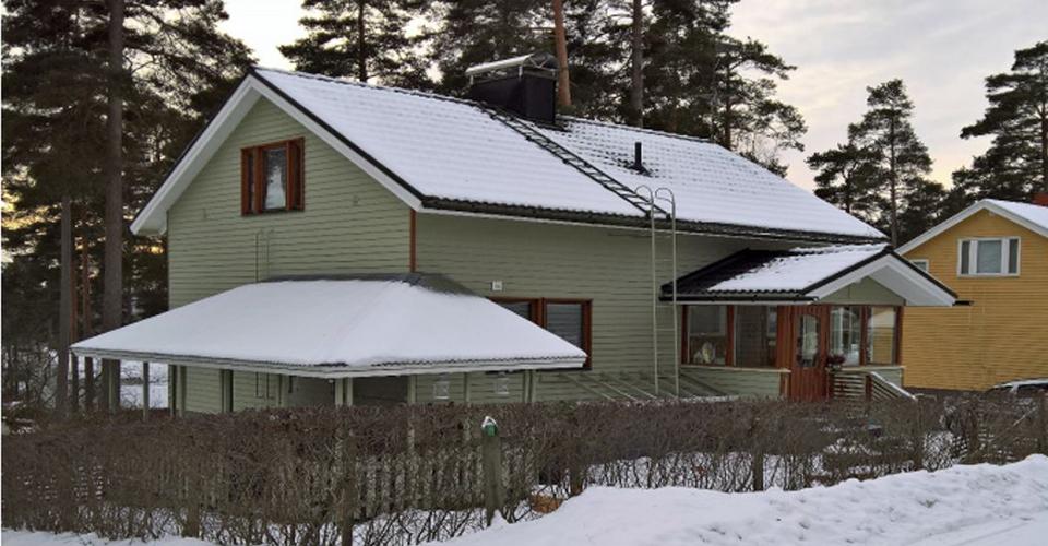
The present study case in this article illustrates a process of preliminary technical planning to upgrade a single-family house in Hämeenlinna, built in 1958. The process has been investigated employing simulations from the IDA Indoor Climate and Energy (IDA ICE) software, version 4.7.1. The general steps were (1) improving the envelope with optimal insulation, new glazing, and airtightness properties; and (2) alternating the heating source. Renovation cost and construction practices were not debated. For each case, the heat losses, energy consumption, and E-value (where significant) were discussed.
Simulation software
IDA ICE is a tool for multizone simulation of the indoor air quality, thermal comfort and building energy consumption. It is primarily developed by the Swedish company EQUA Simulation AB and Swedish academic research partners with the first commercial version dated back to the 1990s. Models in IDA ICE are equation-based on Neutral Model Format, which gives transparent and traceable variables and mathematical equations. The software also offers visualization features with figures, graphs, and animations.
IDA ICE is one of the most common tools in the Nordic market. It has been tested and validated against different international standards, including but not limited to ASHRAE 140, 2004; CEN Standard EN 15255 and 15265, 2007 and the International Energy Agency SHC Task 34 (EQUA Simulation AB). There are a number of recent studies that employing IDA ICE for building energy simulation in renovation, such as La Fleur, Moshfegh, & Rohdin (2017) and Virtanen, Knuuti, & Ahvenniemi (2017). Both examples have demonstrated the software capabilities to produce results correlating to measurement data and validated reference.
Base case model
The simulated building, shown in the main figure of the article, has two floors and a basement, with a net of roughly 110 m2 heated space. The garage in the basement is an unheated space. The building is North-oriented. Its frame is timber while the basement is built mostly from concrete and brickwork. The ground slab is concrete and the drawings show no intentional insulation to the soil. Most of the windows are double-glazed or triple-glazed. The newest ones were installed between the late 1990s and the beginning of the 2000s. The only exception is the window in the laundry room, which is an original single-glazed window. The construction details and the related U-values for the original building are given in Table 1.
Table 1. The construction and the respective U-values for different components in the original building.
| Component | Short specifications | U-value (W/m2K) |
| External wall | Basement – concrete, and brickwork | 0.4 |
| Above ground – wooden stud-frame | 0.54–0.97 | |
| Roof | Roof tiles, ventilated space, wooden ceiling | 0.54 |
| Basement slab | Concrete | 0.58 |
| Windows | 3-pane, 2-pane, and 1-pane | 1.7–2.5 |
| Doors | Wooden frame | 2.28 |
The building case was a typical house from the 1950s, therefore many steps in the modeling work were straightforward or common-practice-based. The description in this study puts more emphasis on how the geometry, zone setting, natural ventilation, and heating system were approached during modelling, which were noteworthy and/or unconventional parts.
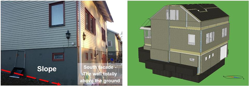
The geometry and shape of the building are crucial factors because they make a direct influence on many parameters, such as the amount of heat loss, thermal bridge, and solar radiation received, just to name a few. In each room in the basement, the external wall part that is in contact with the external ground often loses much less heat than the one that is in contact with the outdoor air. The reason is that the average ground temperature (8oC) is higher than the outdoor air temperature for a major period of the calendar year. In IDA ICE, it is not possible to make a slope for the soil in contact with the basement wall. Therefore, simplification had to be done so that the total area of the ground in contact with the soil stayed the same as in reality (Figure 1).
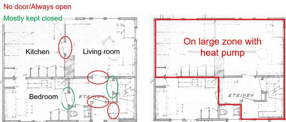
Without thermal zones and surfaces, a building cannot be simulated. In this house, on the first floor, the doors between the kitchen, the living room, and lobby are always opened (Figure 2). Another interesting issue was that there was an air-to-air heat pump. The heat from it naturally went to the rooms and partially to the staircase leading upstairs. In reality, there was no designated heating device for the staircase, the temperature was often cooler. Subsequently, more heat from the heat pump was driven into the staircase area. Nevertheless, in the IDA ICE zone model, the supply heat to zone is distributed evenly with the air, no matter where the heat pump location is. As a result, the kitchen, the living room, the lobby and the staircase was merged together into one large thermal zone, assuming that their heating/cooling setpoints were the same.
The predominant ventilation was natural passive stack ventilation. An air change of ten times per hour was measured with a standard airtightness test. The fireplace was blocked during the renovation in the 1990s. The current owner himself made additional ventilated vents in the basement and on the first floor. The size and location of the vents and openings were manually defined in specific places on the walls to represent the local air flows to and from each zone.
The house used water radiators and a central oil boiler, from the end of the 1960s. It produced direct heat for both domestic hot water (DHW) and space heating. There was no water tank. Thus, the technical plant was modeled with a standard plant model (boiler with an efficiency of 0.87) in IDA ICE. The setpoint for DHW was 55oC while the setpoint for hot water to space heating depends on the ambient temperature. The initial survey indicates that water radiators’ condition was acceptable. Therefore, the ideal heaters were used in the zone model.
The climate file and wind data was the Forssa profile, at the Jokioinen weather station. This is the closest weather station which has a standard weather file (ASHRAE 2013). As window and door properties were not at hand, the technical input, such as U-value and solar transmittance, was taken from the IDA ICE library. The values were compared with references from the Ministry of Environment.
There was no validated documentation available about the details of the current technical system, therefore control logic and equipment data relied significantly on common practices and product datasheet from manufacturers’ websites.
Renovation steps
This case study followed a common procedure for facilitating a project-specific target setting in an early project design stage, to support potential assessment and decision making. The renovation concept aimed to both decrease the heating energy consumption and if viable, increase the renewable energy production of the building. The renovation steps in the model were reflected first with structural refurbishment, then with heating system renewal. These areas are something which owners have significant influence over and there have been studies backing the long-term occupant comfort and cost-effectiveness of such renovation measures.
Structural Refurbishment:
- Replacement of new windows and doors so that maximum value U = 1 W/m2K.
- Additional insulation on the roof (ceiling of living area) and external walls (including porch insulation). The average U-value of all structure changed from 1.6 W/m2K to 0.88 W/m2K. Overall improvement of joints and finishing to avoid thermal bridges.
- An estimation of overall structural renovation and improvement of air resistance would result in a new q50 of around 3 m3/m2h
Heating source replacement:
- Option 1: Replacing the central boiler with district heating (efficiency of heat exchanger = 0.94)
- Option 2: Replacing the central boiler with a water tank and ground source heat pump (COP = 4.6 at rating conditions). A borehole with a depth of 100 m was considered in a typical soil condition and heat exchanger set-up. There were backup electric heating coils in the storage tank. (Note: In order to model this option in IDA ICE, ideal heaters were replaced with water radiators in zones.)
Simulation result
A calendar year simulation was chosen for the period between the 1st of January and 31st of December.
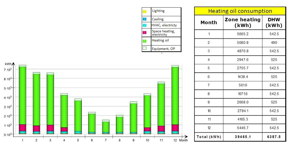
The simulation result at the whole building level showed that the energy required for heating (from both the central oil boiler and the air-to-air heat pump) took up the biggest part of the total energy, more than 95%, while the electrical energy for pumps and auxiliary devices came second. Figure 3 shows a breakdown of the total delivered heat from the central boiler. Only during the summer months, the energy used to produce hot water for domestic usages can be significant compared to the amount of heat required to condition the space. It is obvious that the potential for reducing the space heating energy will be a dominant drive for the renovation design.
The total amount of heating oil predicted by the simulation model was approximately 46000 kWh. Using conventional conversion that 10 kWh equals approximately 1 liter of standard heating oil, the base model would consume about 4600 liters of heating oil annually. For the heating season, the owner reported almost 4900 liters of oil between August 2016 and May 2017.
When looking closer at the zone level, zone heating operated throughout the year, significantly from September until May. As shown in Figure 4, the heat loss through the envelope (external walls, roofs, ground slabs and thermal bridge) was the biggest component (60%) of energy loss of the building. The heat loss by infiltrations tipped at second place, amounted roughly half of the loss through the envelope. These figures corresponded well with the fact that the structure and air-tightness of the building were poor comparing to the current insulation practice and building code.
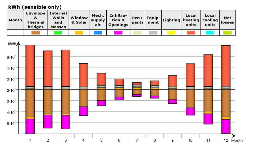
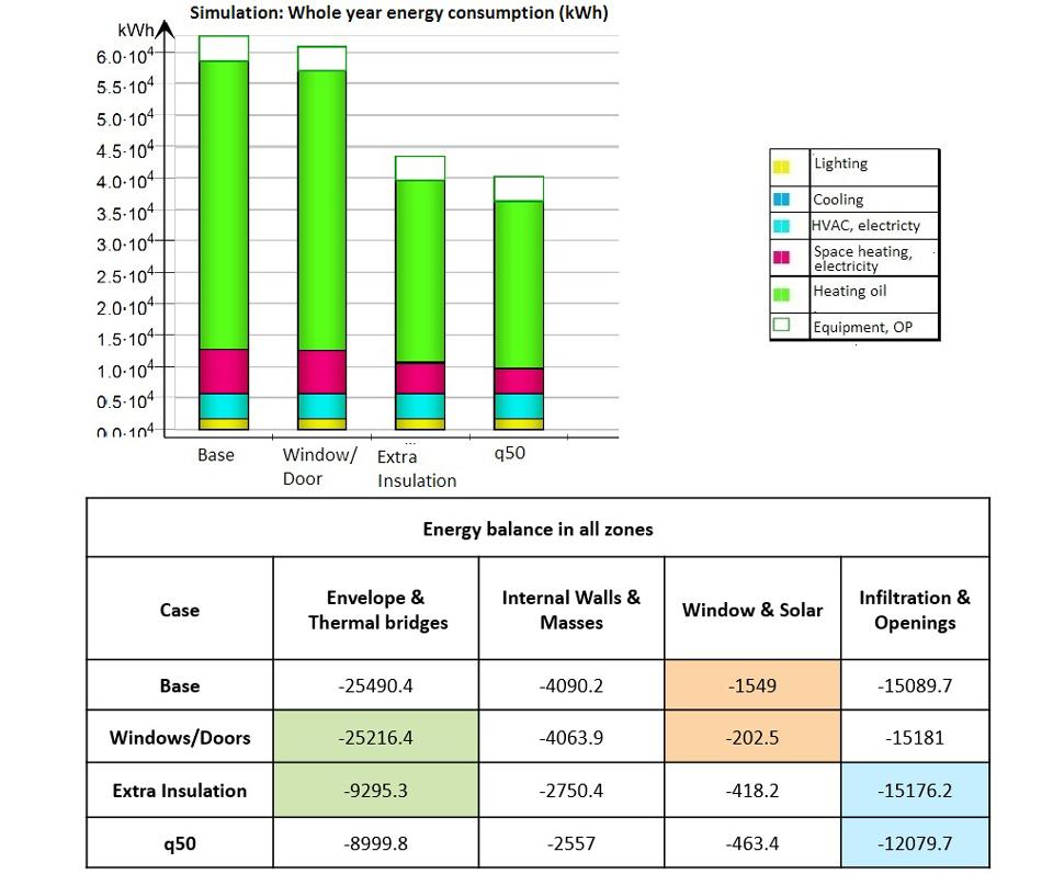
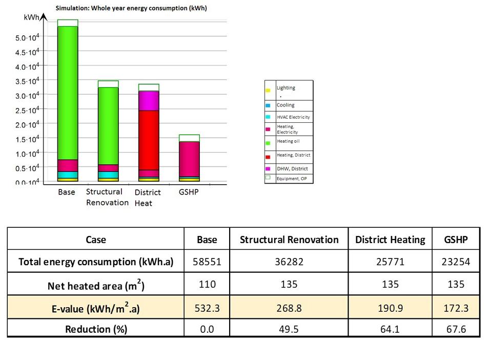
The windows were replaced for the most part in the 1990s when the requirement for U-value of the new ones was already between 1.4 W/m2K. Additionally, the transmission loss through windows was actually significantly compensated by the radiation heat gain (Figure 4). As a result, replacing windows and doors now will not likely bring much improvement to the whole year energy consumption of the building (Figure 5). On the other hand, adding extra insulation helped to halve more than 60% of the heat loss outdoors through the building envelope. Doing so at the same time increases the structural finishing, in another word, improving air-tightness of the whole structure. This would potentially reduce a significant amount of heat loss with the unintended airflow in and out of the building. After the basic step of structural renovation, the energy consumption of the building was predicted to be 60% of the original model (Figure 5).
Then, when considering the heating system replacement, in case of district heating, the oil consumption was replaced by the heat production from the town central network. The substation heat exchanger efficiency was kept at 0.94, higher than the efficiency of the boiler. The total energy consumption of the building would not have any noticeable change but the E-value decreased. The main reason was that the primary energy factor for district heating is 0.7 while the same factor for heating oil was 1.
The second option, using a water tank and a ground source heat pump (GSHP), while delivering the same heat output, could make a significant impact on the input energy. The input energy at this stage for heating was electricity, with a primary energy weighting factor 1.7. However, due to the efficient GSHP and its seasonal coefficient of performance (SCOP) was 2.7, the final E-value was reduced to even lower than the case with district heating.
Both options (district heating and GSHP) would help make the new E-values meet the regulatory requirements on the energy use and E-value improvement in the renovation project. More details can be observed in Figure 6. The increase of the net heated area was due to the extra insulation applied to the whole basement external walls, making the garage a semi-heated space.
Discussion and conclusion
At the beginning of the study, the owners had been interested in the extent to which the modeling result would correlate with the building’s real operation and if it would help to determine the problem in the heating system. On one hand, a consultant later detected the actual problem. The issue was the setting point of hot water production from the boiler being always too high, almost constant at 70oC. The control equipment was stuck, which led the heating oil consumption ramped up. On the other hand, the simulation itself presented an ideal situation where all the set points and control work smoothly. The result proposed a close pattern but with less total consumption of oil for the whole building. Although a direct relationship could not be concluded right away, further investigation and calibration would likely narrow the possible roots of the discrepancy.
The simulation step also showed potential actions in the future renovation. For example, both the new proposed heating systems had a water tank as a storage and balancing medium. In reality, such implementation will help to reduce the risk of having the same problem as the current one, as well as making fault detection easier.
The study case itself was not discussed further with renovation cost or the complete system arrangement. The scope was only to facilitate quick trials by computed software for the calculation to comply with regulation and basic technical changes. For a more holistic study, more measurement data (e.g. monthly utilities, sub-meter recordings, smaller interval data) and a designated monitoring period need to be applied. There are two main reasons. Firstly, the working life of a building can be extended by renovation but how economical between renovating an old building and demolishing it to build a new passive/low-energy house needs to be examined. Secondly, for a detail retrofit planning, a calibrated model with quality simulation result is a must. If monthly data is to be used, the prerequisite is a set of data with a minimum of all measurements from 12 months spanning at least one year (ASHRAE 2002).
Another application of this case study was the pilot module for problem-based and project teaching. So far, the problem has been simplified and introduced to three different undergraduate-level courses: two building physics courses and an energy renovation course. In the near future, a simulation course will be planned for teaching, specifically at the YAMK level (master’s level). Hopfe and Beausoleil-Morrison (2015, 2757–2764.) stated: “…complete and continuous learning cycle that includes exposure to theories and the application of tools from the start can be used to effectively teach building performance simulation.” Such renovation planning processes as the one presented with the same condition are very common in Finnish building stock. The older the house, the more relevant it becomes. It will be beneficial to equip the students with the theories, basic application and practice in order to meet the increasing demand for simulation skills in building industry.
This work has been financed by The European Social Fund and supported by Sheet Metal Centre through the project “Multi-skilled designers in energy technology in building” (2/2016–12/2017).
Authors
Kimmo Hilden, M.Sc (Energy Technology), worked as a Research Engineer at Sheet Metal Centre Research Unit of Häme University of Applied Sciences.
Nhung Nguyen, B.Eng (Construction), is a Research Assistant at Sheet Metal Centre Research Unit of Häme University of Applied Sciences.
References
ASHRAE. (2002). Guideline 14-2002 Measurement of Energy and Demand Savings. Atlanta: ASHRAE The American Society of heating, Refridgerating and Air-conditioning engineers.
ASHRAE. (2013). ASHRAE Standard 169-2013: Climatic Data for Building Design Standards. Atlanta: ASHRAE The American Society of heating, Refridgerating and Air-conditioning engineers.
Clarke, J. A. (2001). Energy Simulation in Energy Design. Reed Educational and Professional Publishing.
EQUA Simulation AB. (n.d.). Validations & certifications. Retrieved 30 June 2018 from https://www.equa.se/en/ida-ice/validation-certifications
European Union. (2012). DIRECTIVE 2012/27/EU on energy efficiency. European Union Parliament and The Council of European. Retrieved 14 December 2016 from https://ec.europa.eu/energy/en/topics/energy-efficiency
Hensen, J. L. & Lamberts, R. (2011). Introduction to Building Performance Simulation. In R. Lamberts & J. L. Hensen (eds.), Building Performance Simulation for Design and Operation. Abingdon: Spoon Press, 7–9.
Hopfe, C. J. & Beausoleil-Morrison, I. (2015). Teaching Building Performance Simulation through a continuous learning cycle. In J. Mathur & V. Garg (eds.), Building Simulation 2015. Hyderabad: International Building Performance Simulation Association, 2757–2764.
Kauppinen, J. (2013). Explanatory Memorandum – Decree on Improving the energy performance of building undergoing renovation or alteration (Unofficial translation). Helsinki: Ministry of the Environment.
La Fleur, L., Moshfegh, B., & Rohdin, P. (2017). Measured and predicted energy use and indoor climate before andafter a major renovation of an apartment building in Sweden. Energy and Buildings (146), 98–110.
Ministry of the Environment (n.d.). Annex to the explanatory memorandum on improving the energy performance of buildings undergoing renovation or alteration. Helsinki.
Neuvonen, P. (2016). Kerrostalot 1880–2000. Arkkitehtuuri, rakennustekniikka, korjaaminen. Helsinki: Rakennustieto Oy.
Statistics Finland. (2012). In Official Statistics of Finland (OSF): Buildings and freetime residences. Helsinki.
Virtanen, M., Knuuti, A., & Ahvenniemi, H. (2017). renZero renovation concept. Helsinki: VTT Technical Research Centre of Finland.
Ympäristöministeriö (n.d.). Energiatodistus opas. Liite 1. Tyypillisiä olemassa olevien vanhojen rakennusten alkuperäisiä suunnitteluarvoja. Helsinki: Ympäristöministeriö.

