Blerand Greiçevci & Newton Avila dos Santos
The world population has grown from approximately one billion to more than seven billion people over the last two centuries, and for the first time in human history, more than half the people on the planet live in urban areas (worldometers, 2018; United Nations, n.d.). The construction and maintenance of these urban centers cooperated to make the construction industry one of the largest in the world. This sector also is one of the largest consumers of natural resources and one of the main generators of residues (Menezes, 2011). This sector is responsible for 25–30% of the waste generated throughout the European Union (EU) – waste composed of various materials such as concrete, bricks, metals, plastic, glass, many of which can be recycled (European Comission, 2018). The EU, through the Waste Framework Directive (2008/98/EC), stipulated that all EU Member States shall take the necessary measures to ensure that by 2020 at least 70% (by weight) of non-hazardous construction and demolition waste is prepared for reuse, recycle or will undergo other material recovery (European Union, 2008).
Glass is one of the building materials and demolition waste that has a good recycling potential (European Comission, 2018) When recycled, it can be used again in civil construction, having several advantageous characteristics: it does not rot, it is resistant to freezing, it is non-toxic and it is resistant to microorganisms and most chemical agents (Khamidulina, 2017) One of the applications that have been verified by researchers is the use of this recycled material in substitution of the natural aggregates, such as stones and sand (Corinaldesi, 2004; Shayan, 2003; Shao,1999). One type of product derived from recycled glass is granulated foam glass (GFG).
Granulated foam glass has a particle density of less than 2000 kg/m³ and therefore it is considered a light aggregate type. It is produced from recycled clean glass and it is characterized by having a porous texture, high silicon oxide content, higher water absorption compared to natural aggregates and low relative density. The GFG compressive strength ranges from 0.8 to 3.5 MPa and the heat transfer coefficient is constant, varying from 0.045 to 0.085 W / m · C (Khamidulina, 2017; EN 13055, 2016).
This study aimed to verify the variation of resistance of concrete when natural aggregates (mixed filler, fine and coarse) are replaced by different percentages of aggregates of foam glass. This variation was studied through concrete compression tests and splitting tests which measure the compressive and shear resistance respectively. The reference concrete used as a comparison was chosen to be C25/30. Natural aggregates were substituted with GFG by 10, 20, 30, and 50%, in volume. This was done based on the recommendations from Arvo Nykänen for finding aggregates ratio for concrete (Nykänen, 1949). For this study, it was decided that the production of concrete would be similar to the one in real environment.
Methodology
The molding and the tests of specimens of concrete were carried out in the Construction Laboratory of Häme University of Applied Sciences, in Hämeenlinna, during April and May, 2018.
Natural aggregates substitutions by GFG were performed based on volume. Five different groups of samples with substitutions of 0%, 10%, 20%, 30%, and 50% were made. Each group consisted of six samples, as described in Table 1. Three samples of each group were molded for the compression tests and three other samples for the splitting tests after 28 days, as specified by EN 206 (2016).
Table 1. Description of test samples
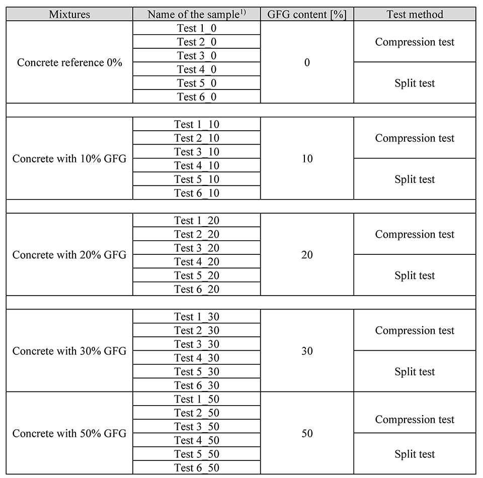
Table 1.
Materials
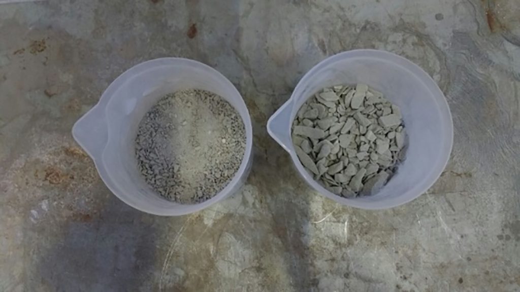
For the preparation of the test specimens, Portland Cement (PC) CEM II/BM (S-LL) 42.5N according to EN 197-1 (2012) was used, water was taken from the public network of the city of Hämeenlinna, and natural aggregates were acquired from a concrete casting company in Hämeenlinna. The shapes used for the molding were cylindrical forms of metal, with a height of 300 mm and a diameter of 150 mm, as recommended by EN 12390-1 (2013). Figure 1 shows the GFG used in this study.
Particle size distribution, foam glass absorption
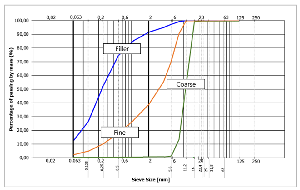
During the study, natural aggregates of three different types (mixed filler, fine and coarse) were used to prepare the specimens. The determination of particle size distribution of the fine and coarse aggregates was performed using the washing and sieving analysis method, according to EN 933-1 (2012).
To determine the apertures of the sieves to be used in each examination, EN 933-2 (1996) was also used. Figure 2 shows the particle size distribution of natural aggregates used.
During the study, granulated foam glass of two different types (mixed filler and coarse) was used to prepare the specimens. The determination of particle size distribution for GFG aggregates was performed using the dry sieving method according to EN 933-1 (2012) and EN 13055 (2016). To determine the apertures of the sieves to be used in each analysis, EN 933-2 (1996) was also observed. Figure 3 shows the particle size distribution of GFGs.

In the foam glass aggregates, the water absorption test was performed. First, two samples were separated and dried to constant mass, then the samples were cooled to room temperature, sieved, weighed, and immersed in water for 24 hours. After the immersion period, the samples had their surface dried and were weighted again, the whole procedure was performed as recommended by EN 1097-6 (2014) for lightweight aggregates. Equation 1 was used to determine the water absorption of the GFG.

where:
m1 is the mass of saturated and surface-dried aggregates, in grams;
m2 is the mass of the dry sample, in grams; and
WA24h is the water absorption after 24 h, in percentages.
Concrete mixing ratios
The ratios of the materials were chosen in such a way that the reference concrete samples (without GFG) could reach the class C25/30, which corresponds to a compressive resistance of 25 MPa for cylindrical shaped specimens and 30 MPa for cube-shaped specimens, according to EN 206 (2016). Calculations were then made to determine the mixing ratios of the other fractions, considering the substitution of materials based on volume. Calculations were made using Arvo Nykänen’s method of finding mixing ratios (Nykänen, 1949).
Table 2 shows the mixing ratios for all fractions.
Table 2. Mixing ratios

Mixing, molding, and curing
Mixing of concrete was done according to EN 480-01 (2014). A concrete mixer of the Collomix TMS 2000 model was used to mix the material (Figure 4).
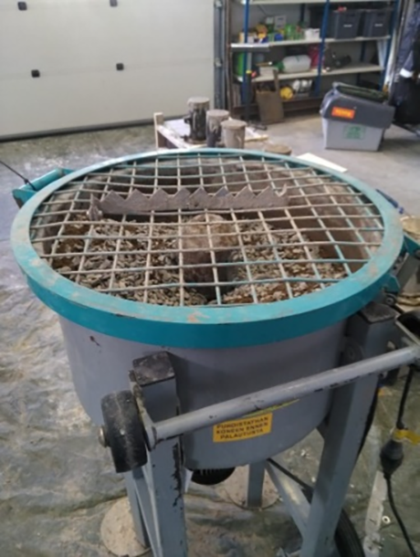
Prior to the molding of the specimens, the molds were greased with a release agent as specified by EN 12390-2 (2009). The molds were filled with concrete and then compacted. The compaction was performed with a poker vibrator, with a frequency higher than 120 Hz. The whole procedure was carried out in such a way that each layer was well compacted, being careful not to over-vibrate, as specified by EN 12390-2 (2009).
After compaction, the excess material was removed from the last layer, and using a steel trowel, the surface was leveled. The samples remained in the molds for more than 16 hours and less than three days, after which, they were demolded and immersed in water, as recommended by EN 12390-2 (2009).
Density of hardened concrete
One of the advantageous characteristics, when natural aggregates are replaced by lightweight aggregates is with regard to the weight of hardened concrete. Therefore, the density of the hardened concrete was checked. The determination of the volume of the specimens was carried out by means of measurements and the determination of the mass was made in the water-saturated specimen, as described in EN 12390-7 (2009).
Test arrangement
The strength resistance of concrete is strongly linked to aggregates and cement paste. The partial replacement of natural aggregates by GFG aggregates may affect the strength of the concrete EN 13055 (2016). Therefore, compressive strength tests and splitting tests to verify the variation of the concrete strength of all fractions were performed, as described below.
Compression tests
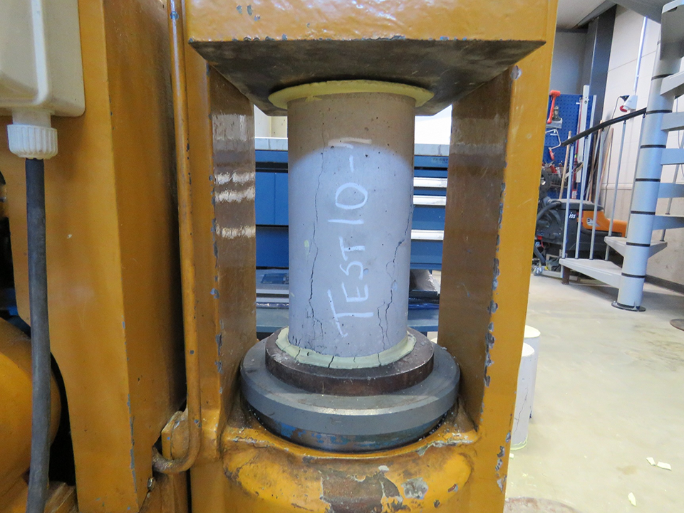
After 28 days of immersion, the samples were removed from the water, had their surfaces cleaned, and all loose particles were removed. The capping was performed when the surfaces of the samples were dry, with capping layers less than 5 mm in thickness. The capping of the samples was carried out using the Sulphur mixture method. The procedure was performed as described in EN 12390-3 (2009). After this, compressive strength tests were performed. For each fraction, three specimens with dimensions of 300 mm in height and 150 mm in diameter were tested, according to EN 12390-3 (2009). Figure 5 shows a compression test being performed.
For this test, an electric drive hydraulic press machine with a mechanical reading module was used according to EN 12390-4 (2000).
Splitting tests
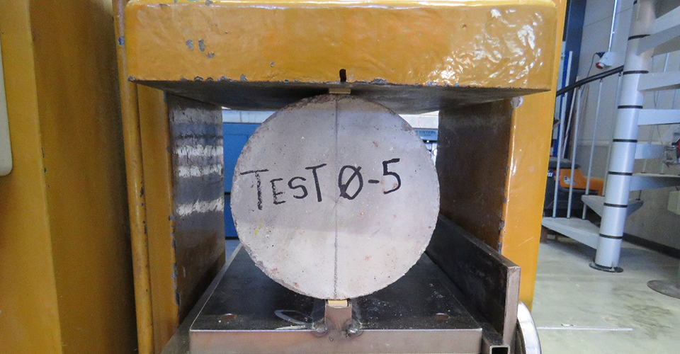
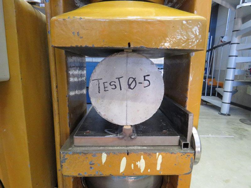
The splitting tests were also performed after 28 days of submerged curing. The specimens were removed from the water, excess moisture from the surface was removed and splitting tests were performed. As indicated by EN 12390-6 (2010), cylindrical specimens with 150 mm diameter and 300 mm height were also used for this test. The reference method specified by EN 12390-6 (2010) was used, i.e. to measure the tensile strength for cylindrical samples, hardboard-packing strips were used. Figure 6 shows a splitting test being performed.
To express the splitting test results, equation 2 was used, according to EN 12390-6 (2010):
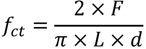
Where fct is the tensile splitting strength, in Megapascals (MPa).
F is the maximum load, in Newtons (N),
L is the length of the line of contact of the specimen, in millimeters (mm), and
d is the cross-sectional diameter, in millimeters (mm).
For each fraction, three specimens were tested according to EN 12390-6 (2010).
Test results and analysis
Compression test results
Table 3 shows the results of the compression tests and characteristic values.
Table 3. Compression test results
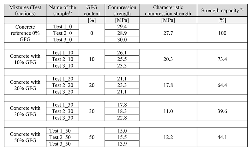
2) The compression strength capacity when compared to the reference concrete.
Characteristic compression strength is calculated using equation (3).

where,
fp = 5 % fractile value (used as characteristic value),
fav = average value of the test results,
σx = standard deviation,
kσ = fractile factor corresponding to the number of tests.
| Number of tests | 3 | 4 | 5 | 6 | 7 | 8 |
| kσ | 3.15 | 2.68 | 2.46 | 2.34 | 2.25 | 2.19 |
Figure 7 illustrates the compressive strength of samples with different contents of GFG in volume. The error bars show the standard deviation and the scattered line shows the tendency of decrease in strength with increased use of GFG.
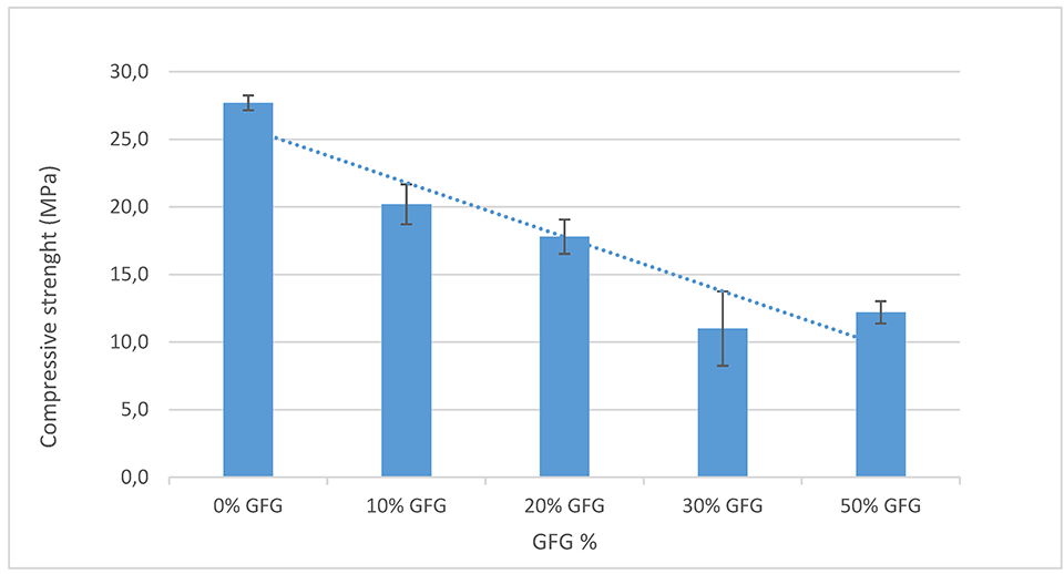
The compression test results show that the higher the percentage of GFG incorporated in the concrete, the lower the compressive strength. This decrease in resistance occurs due to the difference in mechanical properties between natural aggregates and GFG. It was observed from failed samples after the compression test that the foam glass aggregates broke together with the cement paste, while most natural aggregates remained intact.
The test results also show a high standard deviation with samples containing 30% GFG. During the analysis of tested samples, it was observed that most of the failures in the samples with high GFG occurred near the top of the samples1 . To confirm this, the samples with the highest standard deviation and 30% GFG were analyzed more closely. Two first samples show much lower resistance than the third (see Table 4).
Table 4. Compression test results.

________________
1 Top of the sample: Upper part of the test piece, when molded. It should be noted that some samples were inserted into the compression testing machine with the top facing down, which has no effect on the result, since both surfaces were capped.
When Sulphur capping and the cracked part of the samples were removed, visual analysis show that there is a high concentration of GFG particles near the top of the sample. Figure 8a shows the fracture of the sample with high concentration of GFG particles near the top and Figure 8b shows a sample from the same group which had a lower concentration of GFG at the top and has a more uniform fracture throughout the specimen.

Both ”Test 1_30” and ”Test 2_30” failed close to the top of the sample. The third sample, however, ”Test 3_30” had a more distributed failure, and thus it showed a much higher strength capacity.
The higher concentration of GFG in the upper part of the samples could have come as a result of the lightweight of the aggregates floating to the top during the compacting process when the concrete was cast into molds.
Using the results from the compression tests, compressive strength classes for lightweight can be attributed to the samples which had GFG content. The weakest samples have a class of LC 12/13. Although this is a much lower grade than the baseline concrete with grade C25/30, it may still be used for various purposes such as blinding house floors, pad foundations, and non-structural mass concrete in non-aggressive ground situations (EasyMix Concrete, n.d.).
Splitting test results
Table 5 shows the results of the splitting tests which measure the shear resistance of the samples.
Table 5. Splitting test results.
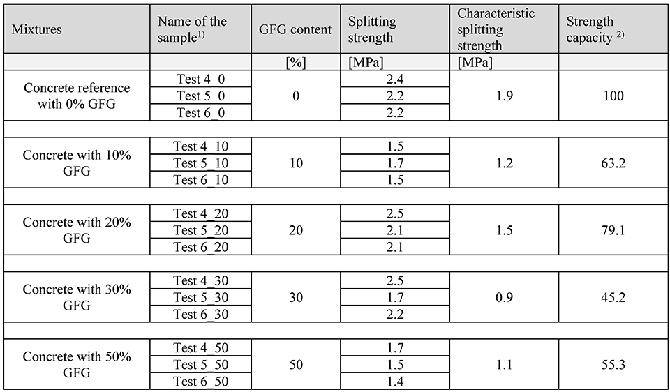
3) The splitting strength capacity when compared to the reference concrete.
Characteristic splitting strength is calculated using equation (4).

where,
fp = 5 % fractile value (used as characteristic value),
fav = average value of the test results,
σx = standard deviation,
kσ = fractile factor corresponding to the number of tests.
| Number of tests | 3 | 4 | 5 | 6 | 7 | 8 |
| kσ | 3.15 | 2.68 | 2.46 | 2.34 | 2.25 | 2.19 |
Figure 9 illustrates the variation of splitting strength with fractions in volume.
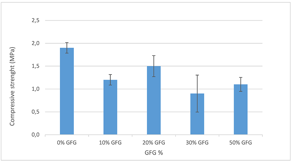
It can be seen from Table 5 and Figure 10 that the results of splitting tests are not consistent. Similarly, as in the compression tests, the samples with 30% GFG content have a higher standard deviation of results from splitting tests. These samples were observed to fail near the top first, during splitting tests as well (see Figure 10).
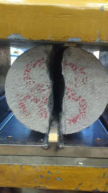
The splitting test which has the ability to break the samples longitudinally made it possible to visualize better the consistency of the sample (Figure 11).
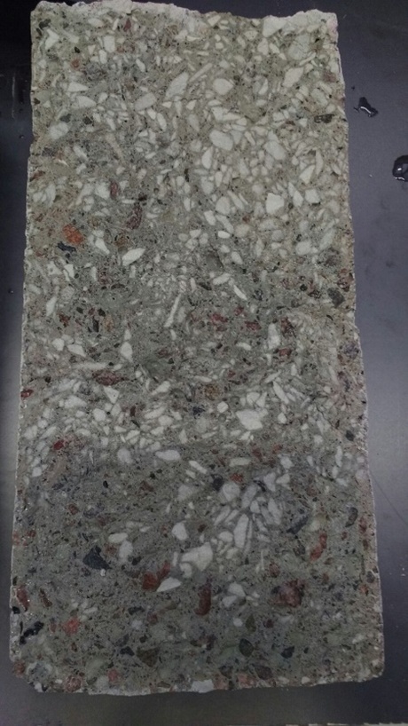
Figure 11 shows clearly a higher concentration of GFG particles at the top of the sample. It should be noted, however, that not all the samples present such a large amount of concentrated GFG at the top, but the tendency towards this is bigger. The presence of a high concentration of GFG at the top could be the primary reason for inconsistent failure modes and results.
Granulated foam glass absorption and density of hardened concrete
The water absorption of the foam glass was analyzed, and it was found to be over 20%. The average value of the two samples analyzed was 23%. This high porosity of the GFG implies the need for more water to be used during concrete production.
Figures 12 and 13 show the density comparison of hardened concrete test samples of all test fractions with different GFG content.
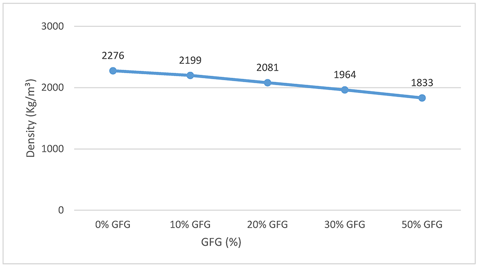
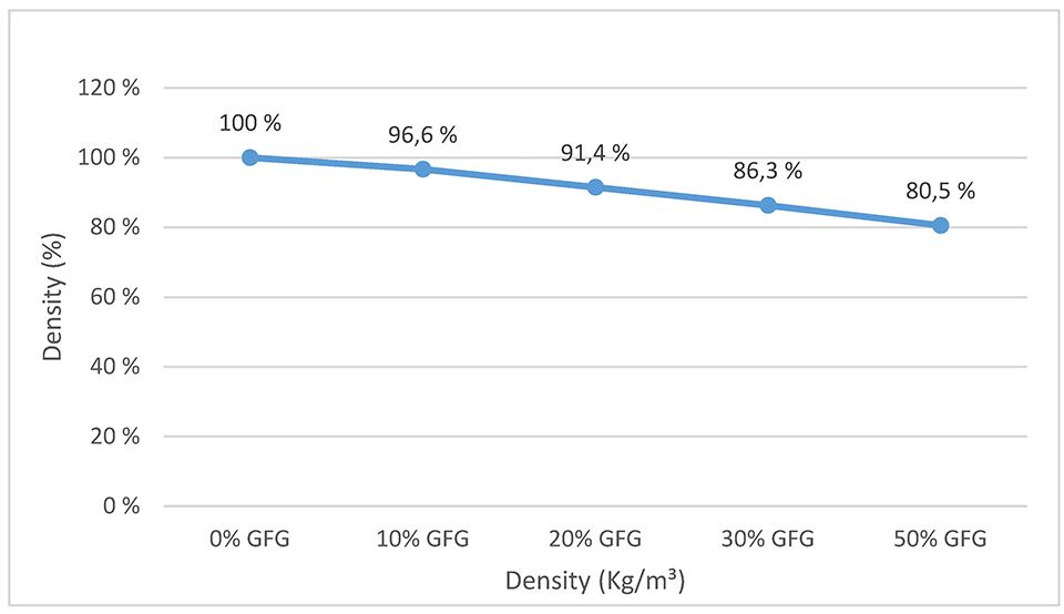
It can be seen that when higher percentages of GFG were incorporated, the density decreased which was naturally expected. This causes a decrease in the weight of the structure, resulting in lower expenses. However, the decrease in weight is not as large as expected. This can be explained by the substitution of natural aggregates with GFG based on the volume. Another contributing factor to the low decrease in density is the absorption capacity of GFG, which causes more water to be used during concrete production.
Conclusion
It was observed during the research that the common (real environment) concrete production process may not be ideal when using light aggregates such as GFG as a replacement of natural aggregates. This is because light aggregates generally have a lower density than the other elements constituting the concrete and may move and concentrate at a location higher up the structure, especially during compaction. Therefore, it is advisable that studies and tests be carried out in order to determine an ideal way to produce the concrete with GFG while minimizing this effect. A more even distribution of GFG in the concrete mixture after casting could lead to more consistent compression and splitting test results and possibly an increase in strength as well.
The compression tests as well as the observation of tested samples show clearly that there is a weakening of the concrete as the amount of GFG incorporated into the concrete increases. This fact is easily understood since the natural aggregate has a much higher resistance compared to GFG. However, despite the observed drop in strength, even the weakest specimens, that is, those made with 50% of the GFG-substituted natural aggregates, presented a class LC12/13 [EN 206 (2016)], which could be used for various purposes, such as blinding house floors, pad foundations, and non-structural mass concrete in non-aggressive ground conditions. In the case of concrete tested with up to 30% content of GFG, its class was determined LC16/18 [EN 206 (2016)] which would even allow its use in light domestic foundations, such as sidewalks and garage bases (EasyMix Concrete, n.d.).
AUTHORS
Blerand Greiçevci, B. Eng (Construction), is a Laboratory Engineer at HAMK Tech Research Unit of Häme University of Applied Sciences. He is pursuing a Master’s degree in Mechanical Engineering at Lappeenranta University of Technology.
Newton Avila dos Santos, is an exchange student from University of Feevale in Brazil and a Laboratory Assistant at HAMK Tech Research Unit of Häme University of Applied Sciences.
REFERENCES
Corinaldesi, V., Gnappi, G. Moriconi, G., & Montenero, A. (2004). Reuse of ground waste glass as aggregate for mortars. Waste Management, 25(2), 197–5201. https://doi.org/10.1016/j.wasman.2004.12.009
EasyMix Concrete. (n.d.). Types Of Concrete And Their Strengths. EasyMix Concrete UK Ltd. Retrieved May 31, 2018 from http://www.easymixconcrete.com/news/types-of-concrete-and-their-strengths/
EN 1097-6. (2014). Tests for mechanical and physical properties of aggregates. Part 6: Determination of particle density and water absorption. Helsinki: SFS Finnish Standards Association.
EN 12390-1. (2013). Testing hardened concrete. part 1: Shape, dimensions and other requirements for specimens and moulds. Helsinki: SFS Finnish Standards Association.
EN 12390-2. (2009). Testing hardened concrete. Part 2: Making and curing specimens for strength tests. Helsinki: SFS Finnish Standards Association.
EN 12390-3. (2009). Testing hardened concrete. Part 3: compressive strength of test specimens. Helsinki: SFS Finnish Standards Association.
EN 12390-4. (2000). Testing hardened concrete. Part 4: Compressive strength. Specification for testing machines. Helsinki: SFS Finnish Standards Association.
EN 12390-6. (2010). Testing hardened concrete. Part 6: Tensile splitting strength of test specimens. Helsinki: SFS Finnish Standards Association.
EN 12390-7. (2009). Testing hardened concrete. Part 7: Density of hardened concrete|. Helsinki: SFS Finnish Standards Association.
EN 13055. (2016). Lightweight aggregates. Helsinki: SFS Finnish Standards Association.
EN 197-1. (2012). Cement. part 1: Composition, specifications and conformity criteria for common cements. Helsinki: SFS Finnish Standards Association.
EN 206. (2016). Concrete. Specification, performance, production and conformity. Helsinki: SFS Finnish Standards Association.
EN 480-01. (2014). Admixtures for concrete, mortar and grout. test methods. Part 1: reference concrete and reference mortar for testing. Helsinki: SFS Finnish Standards Association.
EN 933-1. (2012). Tests for geometrical properties of aggregates. Part 1: Determination of particle size distribution. sieving method. Helsinki: SFS Finnish Standards Association.
EN 933-2. (1996). Tests for geometrical properties of aggregates. Part 2: determination of particle size distribution. test sieves, nominal size of apertures. Helsinki: SFS Standards Finnish Association.
European Commission. (2018, 08 09). Construction and Demolition Waste (CDW). Retrieved 01 January 13, 2019, from European Comission Web site: http://ec.europa.eu/environment/waste/construction_demolition.htm
European Union. (2008). Directive 2008/98/ec of the European Parliament and of the Council on waste and repealing certain Directives. Official Journal of the European Union, 28. Retrieved November 16, 2020 from https://eur-lex.europa.eu/legal-content/EN/TXT/PDF/?uri=CELEX:32008L0098&from=EN
Khamidulina, D. D., Nekrasova, S. A., & Voronin, K. M. (2017). Foam Glass Production from Waste Glass by Compression. IOP Conference Series: Materials Science and Engineering.
Menezes, M. d. (2011). Panorama dos Resíduos de Construção e Demolição [Construction and Demolition Waste Overview]. Revista de Química Industrial [Journal of Industrial Chemistry], 28.
Nykänen, A. (1949). Betonin suhteitus [Concrete ratio]. VTT.
Shao, Y., Lefort T., Moras, S., & Rodriguez, D. (1999). Studies on concrete containing ground waste glass. Cement and concrete research, 30(1), 91–100. https://doi.org/10.1016/S0008-8846(99)00213-6
United Nations. (n.d.). Water and Urbanization. Retrieved November 16, 2020 from https://www.unwater.org/water-facts/urbanization/
worldometers. (2018). Population. Retrieved May 31, 2018 from http://www.worldometers.info/world-population/
Shayan, A. & Xu, A. (2003). Value-added utilisation of waste glass in concrete. Cement and Concrete Research, 34(1), 81–89. https://doi.org/10.1016/S0008-8846(03)00251-5


